
Measure Tools
Planning aid. LUMAMATTERS is a planning aid. Its numbers (illuminance, pixel size, throw distance, overlap) come from maker data and simplified models. They can be wrong. No guarantee of correct data is given. Check critical values against the maker’s spec sheets and on site.
Use the Measure tool to draw dimension lines and notes in the 3D view. Typical uses are projector height, wall width and the distance from a lens to a surface. You place each dimension by hand, with snapping. The app does not fill in dimensions automatically. Dimensions show in the 3D view, in the Outliner and in Properties. They also show on report pictures and in a report table.
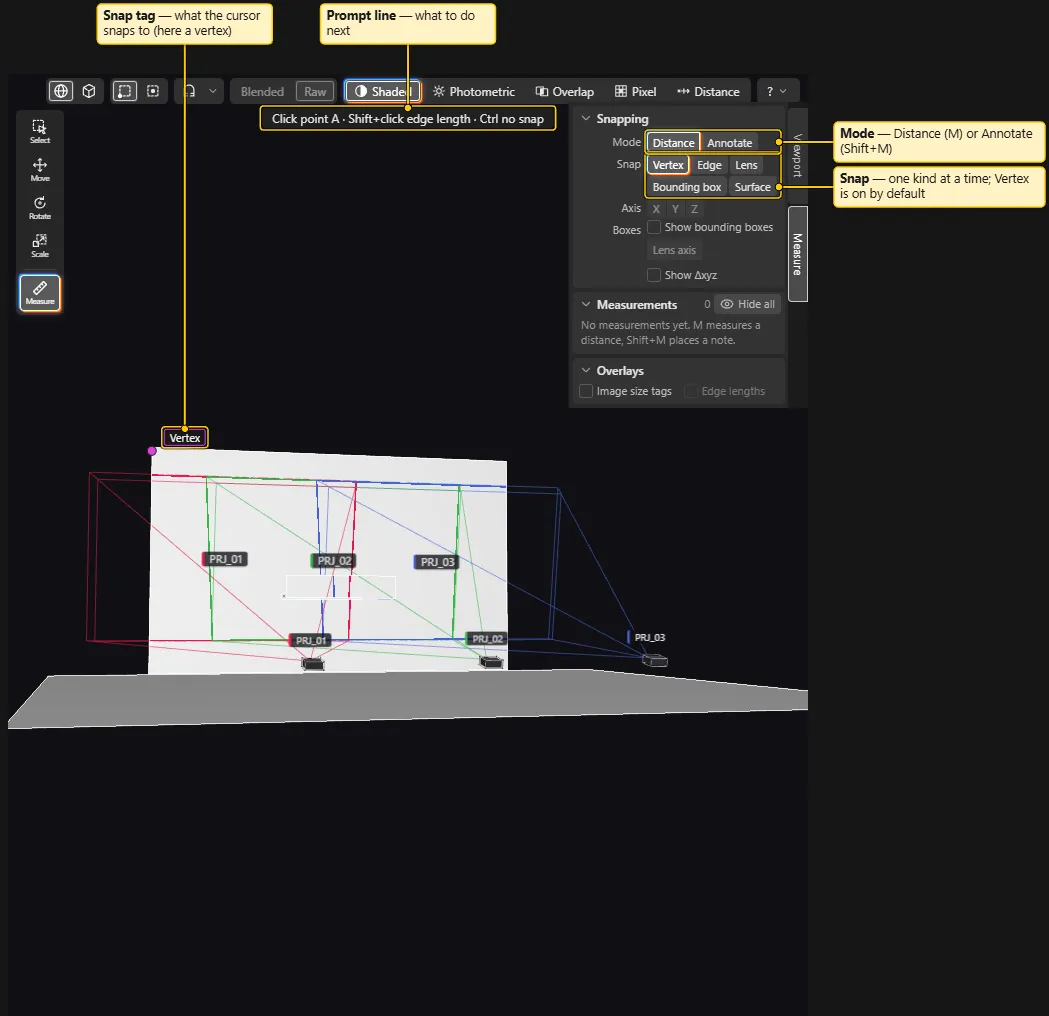
- Click Measure in the tool column. The column is on the left edge of the 3D view, and Measure is set apart from the transform tools.
- You can also press
Mor choose View > Measure. - Press
Shift+Mto start in Annotate mode. - The Measure sidebar unfolds on the right edge of the 3D view. It floats over the view. The view keeps its full size.
- Leaving the tool does not fold the sidebar.
- When the sidebar is folded, it is a small vertical Measure tab. Click the tab or press
Nto unfold or fold it. - Drag the left edge of the sidebar to resize it. The width is 240 to 480 px, and the 3D view keeps at least 320 px.
- Double-click the edge to reset the width. The project does not save the width.
- A prompt line at the top centre says what to do next. For example: “Click point A · Shift+click edge length · Ctrl no snap”.
- After point A, the prompt line shows the lock keys. The active lock is in bold, for example “Locked: Z” or “Locked: plane XY”.
- Press
Escto leave the tool and go back to Select. The keys table below shows the order of theEscsteps.
The Measure tool needs an open project. Navigation works as in every tool. The middle mouse button orbits. The right mouse button pans. The wheel zooms. F frames the selection. The numpad switches viewpoints.
Measure a distance
Section titled “Measure a distance”- Move the cursor over the model. A tag names the snap target, for example Vertex, Edge midpoint, Surface, Lens centre, Projection centre or Box corner.
- Click for point A. A rubber-band line with its value follows the cursor.
- Click for point B. The app creates and selects the measurement.
- The tool stays on, so you can place the next measurement.
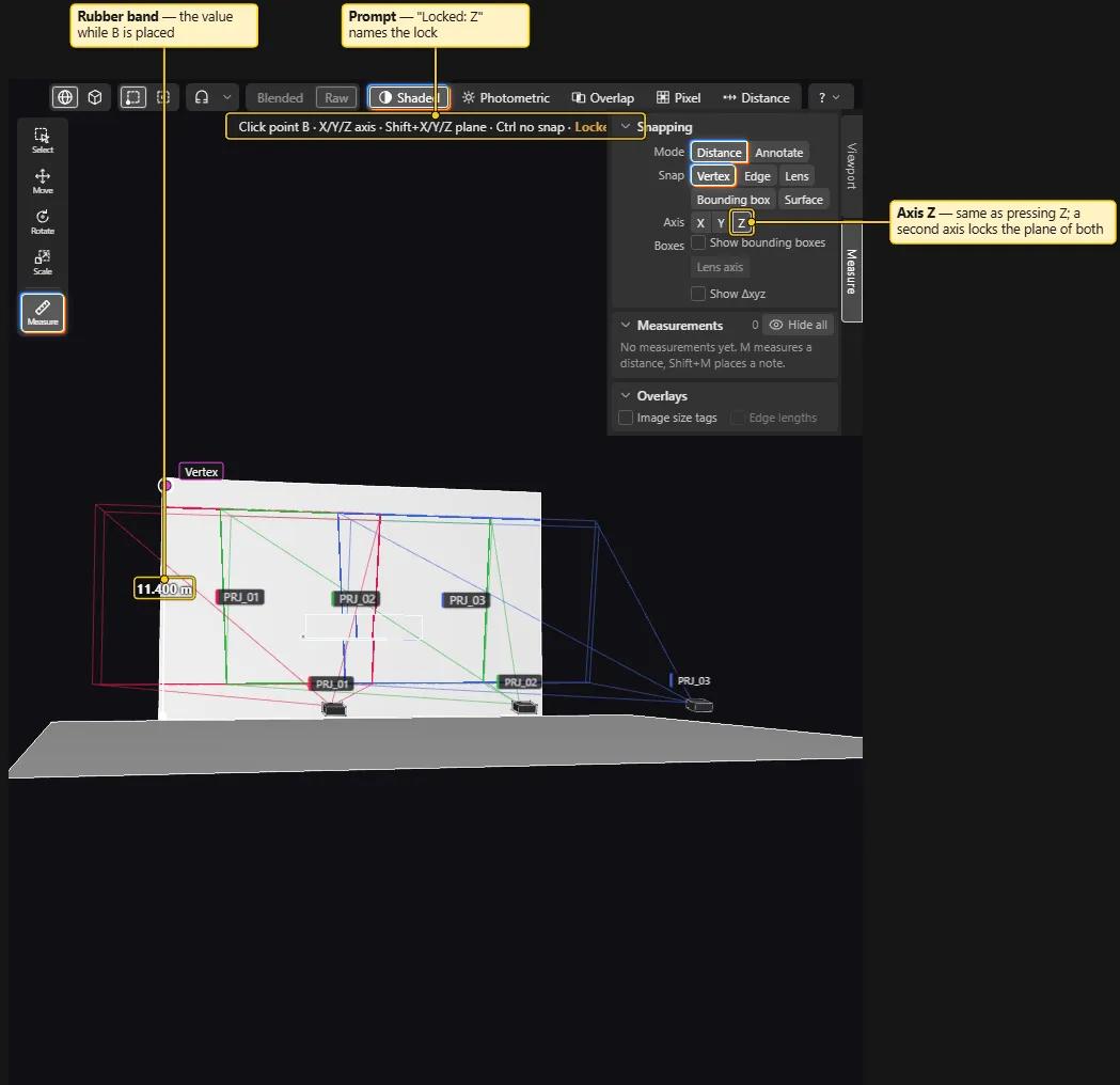
While you place point B, you can use these controls:
- Press
X,YorZto lock the line to that axis. The Z axis is up, as in Blender. The line and the value then use only that component. Press the same key again to unlock. - Press two axis keys to lock to the plane of both. For example,
XthenZgives the XZ plane. A third axis replaces the older of the two. - Press
Shift+X,Shift+YorShift+Zto lock to the plane across that axis (YZ, XZ or XY) in one press. Press the same keys again to unlock. - Click the X, Y and Z buttons in the Axis row of the sidebar. They work like the keys. They are active only while you place point B or drag an end.
- Hold
Ctrlto turn snapping off for that click. - Press
Shift+clickon an edge to measure the length of the edge in one click. This needs Edge snapping (see Snapping below). - Press
Escto drop point A.
Lens axis. Point A can be a lens centre or a projection centre. Then the Lens axis button measures along the centre ray of the projector to the first surface it hits. The value follows when you aim the projector again. If the ray hits nothing, the value shows “no hit”.
Values are in metres with three decimals, for example 11.600 m. A label can also show the difference in X, Y and Z. To see it, switch on Show Δxyz.
Snapping
Section titled “Snapping”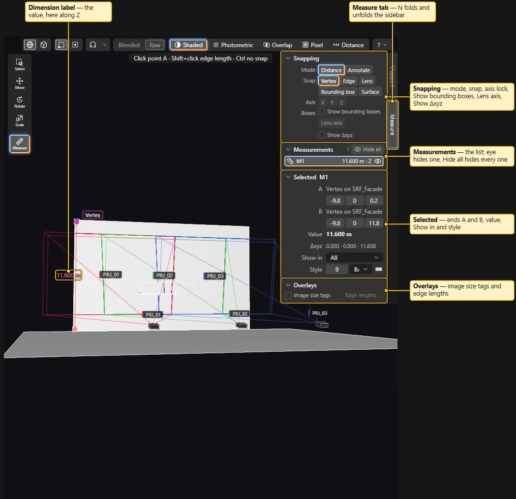
The Measure snap targets are in the Snap steps popover of the 3D view. Open it with the small arrow beside the Magnet button in the top strip. The targets are below the snap steps. The Measure sidebar has no snap controls. It only shows a one-line hint that points to the magnet menu.
Only one target is on at a time, like radio buttons. When you click another target, the first one turns off. Vertex is on when you start the app. The choice is for this session only.
| Snap | Snaps to |
|---|---|
| Vertex | A corner of a mesh. This is the default. |
| Edge | The end or the middle of a feature edge: a border or a real crease. The app ignores diagonals across flat faces. |
| Lens | The lens centre and the projection centre of a projector. |
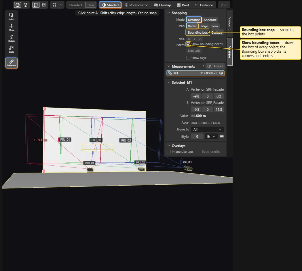
| Bounding box | The centre, corners, edge middles and face centres of the box of an object or of a projector body. |
| Surface | Any point on a visible surface. |
- The targets are strict. With only Vertex on, a click far from any vertex places nothing. Choose Surface to click anywhere on a surface. You can also hold
Ctrlto get a plain surface point. - The lens centre and the projection centre of a projector snap in every mode. The Lens target is the mode that offers only these two points.
- Bounding box snaps to the box points near the cursor. The cursor does not need to point at the model.
- To draw the box of every object and every projector body, switch on Show bounding boxes. This option is in the Tool panel. It is off by default and lasts for the session. It works while the Measure tool is active.
- When two candidates are close, the one nearest on screen wins.
- Hidden objects are not snap targets.
The Magnet button also snaps the Move, Rotate and Scale tools. The default steps are 0.1 m, 5° and a factor of 0.1. The same popover sets the steps. See 3D View.
Edit a measurement
Section titled “Edit a measurement”- Click a dimension line or its label to select it. This works in every tool.
- With the Measure tool, a selected measurement shows handles at A and B. Drag a handle to snap that end to a new place.
X,YandZwork during the drag. One drag is one undo step. - Press
Deleteto delete the selection. PressCtrl+Dto duplicate it. PressFto frame the selected measurements. Delete and Duplicate act on the whole selection (objects and measurements) as one undo step. - A measurement is anchored to the objects it snapped to. When you move or aim an object again, the measurement follows. Undo restores both.
- Type a value in the A or B position fields to turn that end into a free point. The end then no longer follows an object.
- Measurements belong to the project, not to a variation. A measurement on a projector is hidden in a variation that does not have that projector.
The sidebar panels
Section titled “The sidebar panels”
- Tool: Mode (Distance or Annotate), Axis (X, Y, Z), Boxes (Show bounding boxes), Lens axis and Show Δxyz. Show Δxyz is the default for new measurements.
- Measurements: the list. Each row shows a name, a value, a check badge and an eye. The header shows the count and Hide all. Hide all hides every measurement in the 3D view for this session. Click a row to select it (
ShiftandCtrlwork as elsewhere). Double-click a name to rename it. - Selected: this panel shows the selected measurement. It shows where A and B are snapped and the X, Y and Z of each end. It also shows Value, Δxyz, Show in and a short Style row (font size, line ends, colour).
- Overlays: Image size tags writes the image width × height of each projector beside its name, at the aim distance. It needs Labels on. Edge lengths draws the four image edges on the venue with their lengths. It works only while the size tags are on.
Properties of a measurement
Section titled “Properties of a measurement”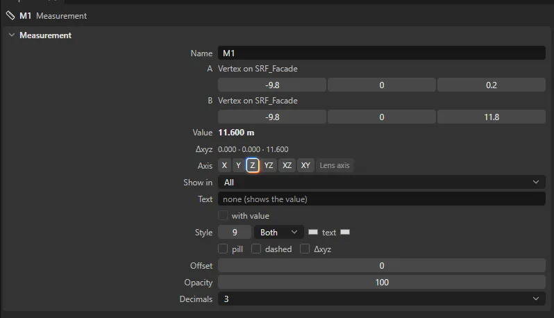
When only measurements are selected, Properties shows all the fields:
- Name, A and B with X, Y, Z (in metres), Value and Δxyz.
- Axis: X, Y, Z, YZ, XZ, XY and Lens axis. A button that does not apply is grey and shows a reason.
- Show in: All or one saved camera. When you look through a camera, the 3D view shows only the measurements for that camera and those set to All.
- Text: replaces the number in the label. with value shows both.
- Style: font size (pt) and line ends (Both, Start, End, None, Ticks). Also line colour, text colour, pill (label background), dashed, Δxyz, Offset (m), Opacity (%) and Decimals (0 to 3).
- Mark checked appears when a check flag is set.
Annotations
Section titled “Annotations”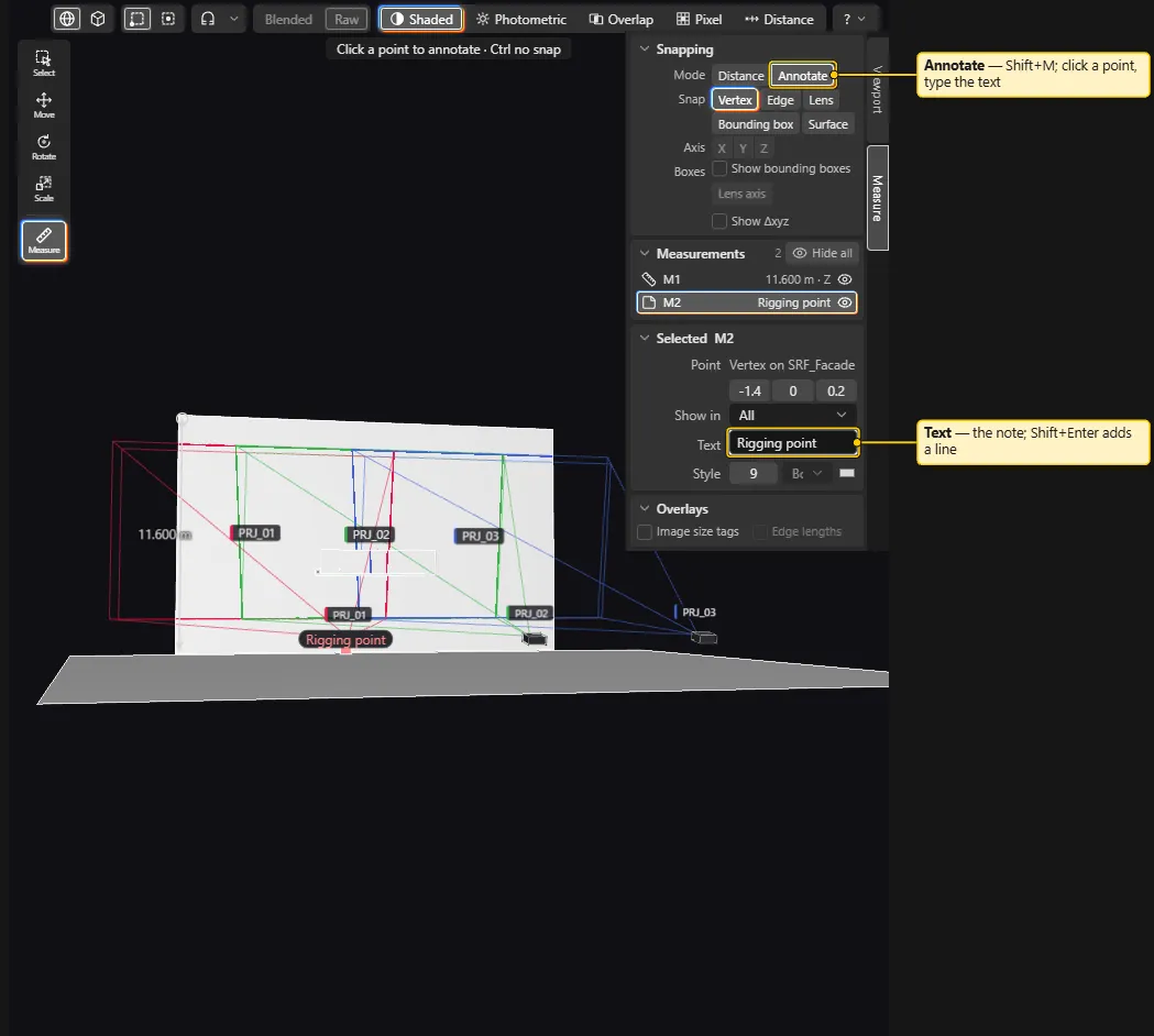
An annotation is a text note on a leader line.
- Press
Shift+M, or choose Annotate in the sidebar. - Click a point. Snapping works as for a distance. Set the targets in the Snap steps popover.
- Type the text.
- Press
Enterto confirm. PressShift+Enterto add a line.
Drag the note to move it. An annotation has the same style, Show in, visibility, lock and follow behaviour as a distance. It shows no number.
In the Outliner
Section titled “In the Outliner”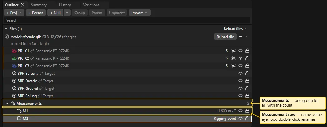
All measurements are in one group, Measurements, at the end of the Outliner. The group shows the count. Each row has a name, the value (for example 11.600 m · Z), an eye and a lock. Double-click a row or press F2 to rename it. You cannot edit or delete a locked measurement. When you select a measurement in the 3D view, the group opens.
In the report
Section titled “In the report”You can put dimensions into the report, on pictures and in a table. For the report editor, see Report and PDF.
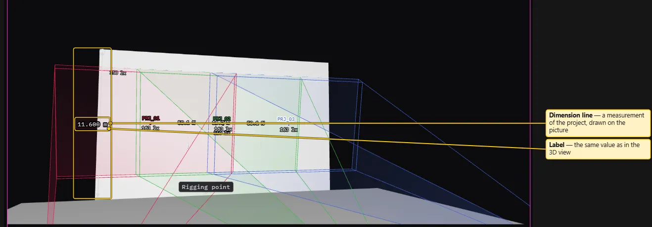
On report pictures. Select a Render block. In its Properties, three switches under the picture options control what the picture draws:
- Measurements: the dimension lines, notes and labels of the project. This switch is on for new pictures.
- Image size tags: the image width × height of each projector at its aim distance. This switch is off for new pictures.
- Edge lengths: the four image edges with their lengths. This switch is off for new pictures.
Each dimension keeps its own style: colour, font size, line ends, dashed, pill, offset, opacity and decimals. The picture setting Label outline applies to labels without a pill. The picture settings Label colour and Label size do not apply to dimensions.
A picture shows the measurements that match it:
- A picture whose source is a saved camera shows the measurements set to All and those set to that camera.
- A picture from the 3D view or from a projector shows only the measurements set to All. This is the Show in field above.
- The picture uses the variation of the report. It leaves out a measurement on a projector that is not in that variation.
- The picture does not draw the parts of a dimension that are behind the camera.
To hide single dimensions on one picture, use the Measurements list in the Properties of that Render block. The list has one checkbox per measurement. Clear a checkbox to hide that measurement on this picture only. You can also click a dimension in the selected picture. Then click the Hide
A measurement with a check flag is amber and dashed in the Report tab, with a “check” badge. The printed copy draws it normally. The report Check list names it as a warning.
In a table. Insert a Table block and choose the source Measurements.

The table has fixed columns: Name, Value, Axis, Δx, Δy, Δz, From, To, Note and Check. It lists every visible distance measurement that resolves in the variation of the report. The order is the order of the sidebar list. The table does not list annotations. If you hide a measurement on a picture, it stays in the table. The Show in setting does not remove it from the table either. From and To say what each end is snapped to. Note holds a text override. A long table continues on new pages, like the other tables.
After a reload
Section titled “After a reload”Measurements follow objects that moved in the model file. Two cases give a measurement an amber check badge:
- The geometry under a snapped point changed, and no match is within 1 mm.
- The object was removed. The measurement then keeps a free point at the last position.
The reload report lists the newly flagged measurements. Check the position. Then press Mark checked, or move an end, to clear the flag. See Blender Export and Import.
| Key | Action |
|---|---|
M |
Measure tool (Distance) |
Shift+M |
Measure tool (Annotate) |
N |
Fold or unfold the sidebar |
X, Y, Z |
Lock to an axis while placing B. Two axes lock to their plane. |
Shift+X, Shift+Y, Shift+Z |
Lock to the YZ, XZ or XY plane while placing B |
Ctrl (held) |
No snapping for that click |
Shift+click an edge |
Measure the length of the edge |
Esc |
Drop point A and the lock. A second press leaves the tool. |
M, N and the tool keys work when the focus is in the 3D view or the Outliner. They do not act while you type in a field. A dimension is drawn on top of the geometry. The geometry does not hide it. The Alt+click probe pin keeps working. See Keyboard Shortcuts.
What the tools do not do
Section titled “What the tools do not do”- They do not measure angles or the area of free polygons.
- They do not give automatic mount-height or distance readouts. For the numbers the app already shows, use Properties > Readouts (Aim distance, Throw distance (maker), Image W × H) and the probe in Summary. See Placing Projectors and Analysis.
- Measurements never change the analysis numbers.
See also
Section titled “See also”3D View, Outliner, Properties, Report and PDF, Keyboard Shortcuts